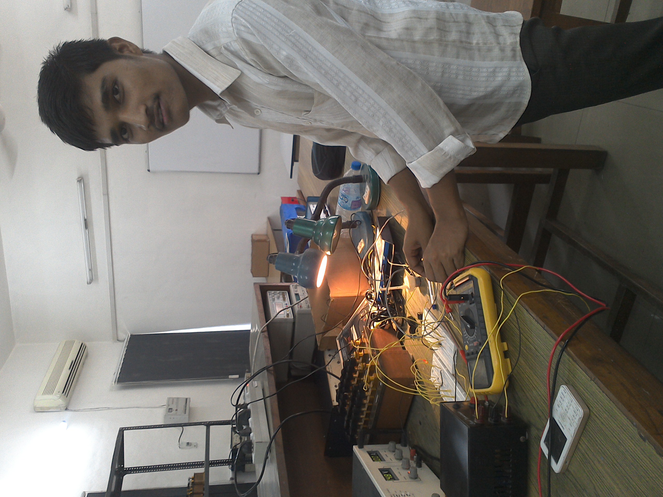
Energy harvesting is fundamentally a game of angles and optimization. During my graduation in 2015, I noticed a critical systemic inefficiency with static solar architecture: panels were bleeding tremendous theoretical energy simply because they couldn't adapt to the earth's rotation. I decided to build a mechanical hardware solution to eliminate this loss.
What is a Solar Tracker?
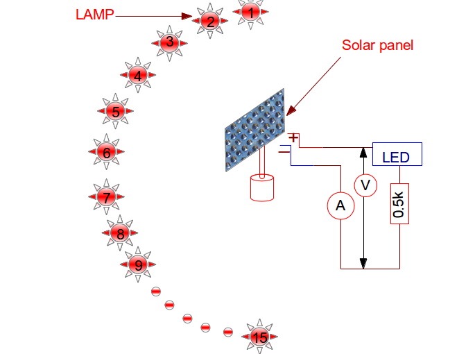
A solar tracker is an automated electromechanical system designed to continuously calculate and adjust the panel's physical trajectory, maintaining a perfect 90-degree incidence angle with the sun. The logic is simple: if you want maximum energy output, the system must actively follow the source.
Why is a Tracker Systemically Necessary?
The core math of energy loss is governed by the cosine of the incidence angle. Maximum yield is only obtained when direct sunlight hits the photoelectric surface at exactly 0 degrees. When a panel is structurally fixed, the sun's relative position shifts constantly.
A 60-degree offset doesn't just look bad—it literally destroys 50% of your energy yield before it even hits the battery. A tracking system engineered to eliminate this variance isn't just an accessory; it's a mathematical requisite for maximum efficiency.
Types of Solar Trackers & Scaling Logic
1. Single-axis Trackers (This Prototype): Restricted to movement along one geometric axis. For this college thesis, I engineered and physically built the single-axis analog prototype to prove the concept organically.
2. Dual-axis Trackers (The Scaling Conclusion): Tracks the sun across both vertical and horizontal planes. Upon successfully proving the closed-loop analog logic on a single axis, scaling this to a dual-axis system mathematically requires zero new logic—you simply duplicate the exact same LDR and Op-Amp differential circuit for the perpendicular Y-axis.
The Physics of Energy Loss
Sunlight consists of two components: Direct sunlight (carrying roughly 90% of the harvestable energy) and Diffuse sunlight (ambient, scattered energy). Since direct sunlight contains the overwhelming majority of the power, securing direct hits for the maximum duration of the day is critical.
| Angle (°) | cos(i) | Mechanical Energy Loss (%) |
|---|---|---|
| 0 | 1 | 0% |
| 15 | 0.966 | 3.4% |
| 30 | 0.866 | 13.4% |
| 45 | 0.707 | 29% |
| 60 | 0.5 | 50% |
| 75 | 0.258 | 74% |
| 90 | 0 | 100% |
Raw Logic Over Microcontrollers
Most engineering students approach this problem by throwing microcontrollers at it. They use Arduinos, write complex C++ loops, and buy expensive digital development boards.
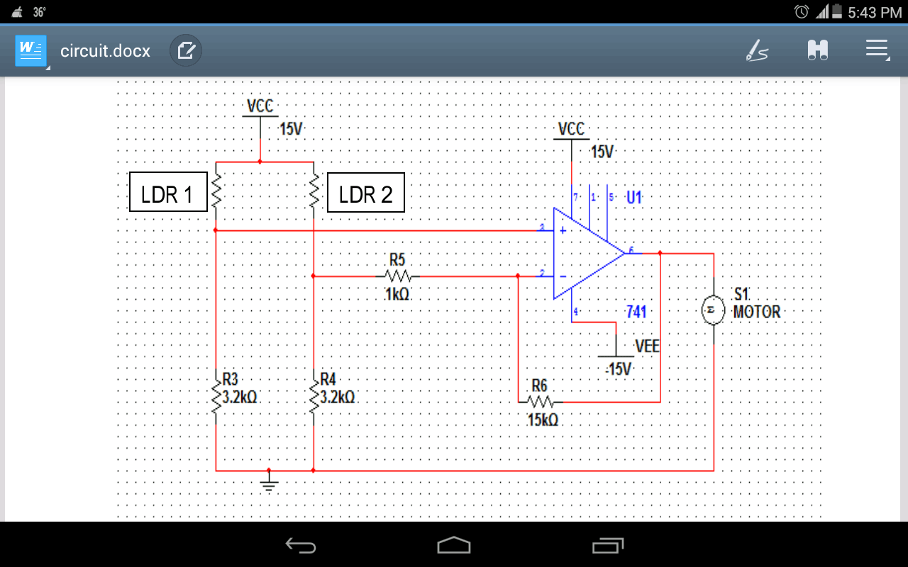
I wanted to build a raw, fundamental electronic system without the crutch of digital programming. This project was built entirely on analog logic gates using a simple Op-Amp (IC 741) to create an elegant, highly budget-friendly differential voltage comparator.
Hardware & Components
- LDR (Light Dependent Resistor) arrays
- Op-Amp (IC 741) Logic Brain
- High-torque DC Gear Motors (25-35 RPM)
- 12V Monocrystalline Panel & Battery unit
- Indicator LEDs & Precision Resistors (1k, 3.2k, 15k ohm)
The Assembly Architecture & Resource MacGyvering
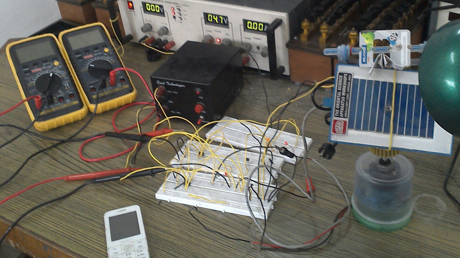
At the time of assembly, professional fabrication wasn't an option, so the physical hardware was engineered entirely out of upcycled materials. The motor housing and base stand were constructed from a repurposed plastic kitchen spice box. The precise sensor array mounted to the top edge of the solar panel was built using use-and-throw plastic pens as structural mounting arms glued to an empty, discarded SIM card holder frame. A simple folded paper strip sits perpendicularly on the SIM frame, acting as the vital opaque shadow-divider between the two LDRs. The analog logic circuit sits entirely decoupled on the breadboards to the left, feeding differential power to the motor assembly.
- Assemble the analog voltage comparator circuit directly onto a breadboard matrix.
- Configure LDR arrays with physical opaque dividers to create distinct directional light differentials.
- Feed the LDR outputs directly into the Op-Amp running in differential mode.
- Bridge the Op-Amp outputs to route mechanical power to the DC tracking motors.
The Closed-Loop Automation System
The entire operation functioned as a self-regulating, closed-loop system:
- If LDR-1 senses higher light intensity, its internal resistance drops. The resulting voltage spike hits the Op-Amp, driving the motor to rotate towards LDR-1.
- If LDR-2 senses the light, the differential reverses, and the motor spins in the opposite direction.
- The Equilibrium State: When both LDRs receive equal light (meaning the panel is perfectly aligned 90-degrees to the sun), the differential voltage resolves to exact zero. The motor instantly stops.
The Systems Perspective
Building this prototype wasn't just about passing a college physics lab; it was my earliest deep dive into automated systems. By relying purely on the physical properties of Light Dependent Resistors and analog logic, I built a system that managed its own state and corrected its own mechanical errors naturally—zero digital programming required.
It was incredibly cheap, overwhelmingly effective, and reinforced my core belief: the best systems are the ones that fundamentally regulate themselves.